
XFA with FRU packing RoHS Compliant - 5341541-2 - GE MRI PARTS 5341541-51 - XFA with FRU Packing
Figure 2 is a plot of the calculated magnetic coupling coefficients between the two coplanar rectangular coils and the two coils on the cylindrical former, as a function of the distance between the center of the coils, l. The curves were obtained by numerical integration of the analytical expressions of magnetic coupling derived for the two geometries. The results obtained were in both cases normalized to the values at zero separation (complete overlap, l = 0). These plots were used to estimate the overlap distance between the two-coil loops in both the cylindrical and planar arrays to ensure nulling of their mutual inductance.
Clinical scanner compatibility allows these RF receiver probes to be used with conventional pulse sequences and imaging protocols, such as cardiac tagging or CINE phase contrast. The arrays have an inexpensive and flexible design that enables them to be used for various imaging applications including the heart, spine, and pelvis.
HiddenName* Name* First Last Phone #* Email* Company* Time Frame*Immediate1-3 Months3-6 Months6-12 MonthsDon't Know YetHave you ever worked with us before?*YesNoMessage*EmailThis field is for validation purposes and should be left unchanged. Submit
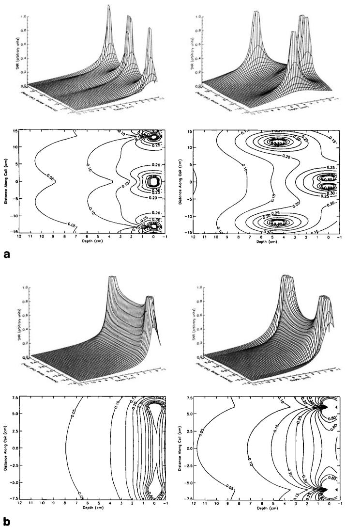
The theoretically estimated plots of the SNR performance of the cylindrical and the planar array, shown in the surface and contour plots of Fig. 4, were further verified by imaging a phantom. Axial images were acquired using the two phased arrays independently, as shown in Fig. 5. A spin echo pulse sequence was used with the following imaging parameters: TR = 1000 ms, slice thickness = 3 mm, 256 × 256 acquisition matrix, TE = 11 ms, FOV = 36 cm. It is noteworthy that both the extent as well as the penetration depth of the high SNR region is greater in the cylindrical array.
Table 2 shows quantitative SNR measurements taken from four different regions of the left ventricle as illustrated in Fig. 7, using the body coil, a two-loop commercially available flexible surface coil, a commercially available four-loop planar pelvic phased array, the cylindrical phased array, and the combined cylindrical-planar phased array assemblies. The planar array was placed on the back of the chest at the level of the heart with the long axis of the array oriented left-to-right. The SNR was calculated using the mean of a 100-pixel region of interest centered at the desired location in the image, and by the corrected value of the standard deviation of the background noise signal (18). Sum-of-squares images were reconstructed for the phased arrays, and magnitude images were reconstructed for the body and flexible coils.
In this paper, we present a four-loop phased array receiver coil used for 1H imaging of the human heart. Two loops are mounted on a cylindrical former to conform to the shape of the chest. This maintains high sensitivity and field homogeneity up to the posterior wall of the heart. Further improvement of the signal performance at the posterior wall of the heart is achieved by interfacing the cylindrical coil with an additional planar coil array, placed on the posterior side of the thorax, at the level of the heart. The intrinsic features of a phased array system ensure enhanced signal-to-noise (SNR) performance with depth over other types of conventional surface coils, while maintaining an increased field of view (FOV). This makes this prototype coil optimum for high resolution cardiac imaging.
Secure .gov websites use HTTPS A lock ( Lock Locked padlock icon ) or https:// means you've safely connected to the .gov website. Share sensitive information only on official, secure websites.
where σ is the average sample conductivity, Ei(r) and Ek(r) are the spatially dependent varying electric fields induced in the sample by a linearly polarized magnetic field due to flow of a unit current in the coil.1
Plot of the magnetic coupling coefficient in the planar and cylindrical phased arrays as a function of the separation between the center of the coil loops, l An overlap distance of 3.2 cm is required for the loops in the cylindrical array and a distance of 1.6 cm for the loops in the planar array to null their mutual inductance.
The introduction of single breath-hold CINE MRI (1, 2) has dramatically improved the quality of cardiac images through the significant reduction of blurring and ghosting generated from respiratory motion. This opened new avenues for producing high spatial and temporal resolution images. At the same time, however, it resulted in images with lower SNR due to the use of ultra-fast gradient echo pulse sequences (low flip angles, wide receiver bandwidth, short TRs). Consequently, the use of a specialized RF surface coil is deemed necessary to achieve an enhanced receiver sensitivity.
The RF field, B1, in Eq. [4], represents a two-element vector for any given point in the axial or sagittal plane of interest and R12, is a 2 × 2 matrix describing the mutual resistances of the coils. The resistances of the coils in the array configuration and in isolation were measured yielding an electric coupling coefficient of 0.288 ± 0.02 for the cylindrical array compared with 0.314 ± 0.03 for the planar array on the chest, as shown in Table 1.
Both loops, in each of the two phased arrays, were tuned to 63.86 MHz independently and matched to 50 Ω when loaded. Each of the loops was connected to a separate preamplifier, receiver, and A/D. To prevent any interaction between the RF transmitting coil and the receiver coils during the excitation phase (10-13), PIN diode blocking circuits were implemented as shown in Fig. 3. These formed high impedance resonant blocking networks on the coil during the transmission phase, preventing any circulating currents. This blocking action was activated on forward biasing the PIN diodes (UM9415, Microsemi, MA) with a DC current provided by the scanner's driving board. Bazooka balun circuits were employed (14) to minimize possible circulating currents on the outside conductor of the cable, providing an inherent way of balancing the system. The capacitance was distributed around each of the coil loops (with six breaks) to minimize dielectric losses (15).
Address correspondence to: Elliot R. McVeigh, Ph.D., Medical Imaging Laboratory, Department of Biomedical Engineering and Radiology, Johns Hopkins University School of Medicine, Baltimore, MD 21205.
Short axis views of the heart of a normal volunteer with different coils: (top left) body coil, (top right) flexible surface coil; (mid left) Cylindrical phased array, (mid right) planar pelvic phased array; (bottom left) combined planar and cylindrical phased arrays, (bottom right) tagged image of an in vivo human heart at a 32-cm FOV in a short axis view at mid-systole.
Coil geometries of the constructed phased arrays. All coil loops have a width d of 12.25 cm, length s of 13.75 cm (centerline dimensions), separation l, and a conductor width of 1.25 cm. The array on the cylindrical frame conforms closely to the chest.
Therefore, optimum SNR performance is achieved if the geometry of the coil employed assures a maximized B1 field sensitivity but also if it minimizes the electric coupling coefficients.
Images in the xy plane taken with the two phased array coils on a cylindrical conductive water-filled phantom (FOV = 36 cm). (top) Sum-of-squares axial image using the cylindrical phased array; (bottom) Sum-of-squares axial images using the planar phased array.
DirectMed Imaging Subsidiaries include LBN Medical & ScanMed. Technical Prospects and Titanium Medical Imaging are now DirectMed Imaging.Privacy Policy – Terms of Sale – Terms of Sale for Training
The authors thank Mr. Ivan Stepanov for his help with the construction of the coils and assembly of the electronics; Tony Vance for his help with the Signa scanner; Dr. L. Axel and Zahi Fayad for their useful suggestions regarding the coil construction; Drs. C. Hardy, P. Roemer, and P. Barker for their advice; and Dr. Carlos Lugo-Olivieri for his help with the imaging protocol.
Using a rapid gradient echo pulse sequence, short axis images of the heart were obtained from a normal male volunteer (150 pounds) in the supine position, at three different locations from base to apex spanning the entire myocardial region. Informed consent was obtained from the volunteer and all imaging conformed with the guidelines of the institutional review board. The FOV was 32 cm, slice thickness = 10 mm, TR = 6.5 ms, TE = 2.3 ms, 256 × 128 acquisition matrix, 1 NEX. High resolution tagged images of the left ventricle were also obtained using a breath-hold tagging pulse sequence (2). Examples are shown in Fig. 6.
Because the difference in the measured noise correlation for the two coil arrays is small, a conservative estimate of 0.3 was used for this calculation (3). Figure 4 shows the relative SNR in the axial and sagittal planes determined using Eq. [4].
All experiments were conducted on a 1.5 T Signa (GE Medical Systems, Milwaukee, WI) imaging system equipped with self-shielded gradient coils and the multicoil option. The body coil was used throughout for transmission, ensuring a homogeneous field for excitation over the required FOV. A schematic diagram of the phased array assemblies and associated electronics is given in Fig. 3.
A prototype cardiac phased array receiver coil was constructed that comprised a cylindrical array and a separate planar array. Both arrays had two coil loops with the same coil dimensions. Data acquisition with the cylindrical array placed on the human chest, and the planar array placed under the back, yielded an overall enhancement of the signal-to-noise ratio (SNR) over the entire heart by a factor of 1.1–2.85 over a commercially available flexible coil and a commercially available four-loop planar phased array coil. This improvement in SNR can be exploited in cardiac imaging to increase the spatial resolution and reduce the image acquisition time.
where B1 is a 1 × n element complex vector describing the transverse magnetic field from both coils at that point and Rik is the noise resistance matrix as described above.
The improvement in SNR by both the cylindrical and the combined cylindrical and planar arrays, as evidenced by the increased signal at the inferior wall of the heart, can be used in clinical imaging to increase spatial resolution or to reduce image acquisition time, an important parameter in breath-hold CINE cardiac imaging.

The cylindrical phased array was constructed on a former of radius 17.5 cm. This was designed to fit the human torso even for a large person.
The noninteracting nature of phased array coils stems from the fact that when different current carrying coil loops i and k are overlapped appropriately, their mutual inductance, Mjk, reduces to zero. This is simply because the flux linkages through the coil loops sum to zero for a specific loop overlap, determined by the loop size and coil geometry.
In myocardial tagging (19), the trade-off between the enhanced SNR provided by the combined array and an increased spatial resolution will yield high resolution tag patterns for the evaluation of strain estimates in the clinical setting. The phased array also increases the duration of the tag stripes by increasing the CNR between the tag and the background myocardium.
(a) Theoretical SNR surface (top) and contour (bottom) plots for the individual planar (left column) and cylindrical (right column) coil arrays through an axial slice at the center of the coil (z = 0). (b) Theoretical SNR surface (top) and contour (bottom) plots for the individual planar (left column) and cylindrical (right column) coil arrays through a sagittal slice bisecting the two overlapping coil loops in each array.
Degradation of coil sensitivity with depth gives rise to the low SNR performance at the inferior heart wall. The signal performance, especially at regions deep within the chest wall, was thus improved by interfacing the cylindrical coil with the planar array placed on the back of the human volunteer. This provides a flexible design, allowing the planar array to be used independently for pelvic and spine imaging.
The SNR performance of the prototype cylindrical and planar phased arrays are demonstrated both with theoretical simulations and with phantom imaging. We also demonstrate the increased SNR performance of the combined cylindrical-planar array over a commercially available flexible surface coil and a commercially available planar four-loop pelvic phased array on the heart of a normal human volunteer using a fast gradient echo sequence.
The geometric configuration of the cylindrical array was also of great importance for cardiac imaging. It conforms closely to the human chest, even for large patients, and it improves patient comfort because imaging can be performed with the patient in the supine position.
Name* First Last Email* Phone*Which of these best describes you?*ConsultantEducationEquipment DealerFinancial InstitutionHospitalMobile ProviderOEMParts SupplierService CompanyModality*C-ArmC-Arm TableCath/AngioCRDEXADR PanelImagerLinacLithoMammoMRINuclearPACS SolutionPETPET/CTSPECT/CTPortable X-RayRad RoomR/FUltrasoundManufacturerGESiemensPhilipsToshibaWhat type of service do you need?* Model / Series* Project Timing*Immediate1-3 months3-6 months6-12 months12-24 monthsDon't know yetAdditional Comments Submit
Analytical expressions for the mutual inductance, M12, of a linear and a cylindrical two-coil array, shown in Fig. 1, were derived from the line integrals of the vector potential A in each geometry (5, 6). In both assemblies, each of the loops was choosen to be 13.75 × 12.25 cm (centerline dimensions) to achieve optimum SNR for detecting an object at a depth of 14 cm (7, 8).
A prototype phased array receiver on a cylindrical former suitable for high resolution cardiac imaging on a clinical 1.5 T GE Signa scanner has been demonstrated. This design was optimum for cardiac imaging compared with other coils, including a planar pelvic phased array comprised of the same number of coil loops with the same dimensions.
Equation [4] was used to predict the SNR performance of each of the two arrays. Therefore, for the SNR calculation, the relative sensitivity of the coil can be determined by the calculation of the magnetic field produced by the coil system due to a constant input current. This was derived from the Biot-Savart Law for each of the individual coils.
Given that the dominant loss mechanism in an NMR experiment is the sample, the noise resistances between the coils i and k used in combination, Rik (i ≠ k), can be determined (5, 9) as the inner product of the spatially varying electric fields of the coils over the volume V of the sample as:
Part price is only one factor to consider in overall part cost. Consider the other factors in this video before you buy!
Radiofrequency surface coils have previously been used to enhance the SNR from the myocardium (3). The rapid decrease of the sensitivity with distance from the coil, as well as the geometric constraints imposed by the shape, size, and position of the heart with respect to the thorax, recently led to the introduction of a specialized human cardiac phased array coil for 31P spectroscopy (3) and 1H imaging (4). In their design, Hardy et al. (3), wrapped the left side of the array upward to conform closely to the shape of the human torso, increasing the extent of the high sensitivity region compared with previous surface coil designs.
Because of its inhomogeneous sensitivity pattern, a surface coil induces spatially dependent amplitude and phase variations in the received signal from any voxel (16) within the FOV. Compensation for these effects can be achieved in phased array systems through the use of detailed RF field maps (17). The fact that this procedure is sample-dependent makes this impractical and difficult to implement in human cardiac imaging. As a result, the sum-of-squares reconstruction algorithm was used (5).
This research was supported by the National Institutes of Health grants HL45683 and HL45090. Chris D. Constantinides is funded through a United States Information Agency (USIA) Biomedical Engineering Scholarship.
The fundamental goal in the development of a mutually coupled coil system is the determination of a configuration that optimizes the SNR over the desired FOV. In a linearly polarized system, the relative SNR at any point in space can be approximated by:
Schematic diagrams of the phased array assemblies and associated electronics. The coil resistance is 50 ± 10 Ω at resonance, with the sample present so no other matching network was employed. Cable resistances are 50 Ω. λ denotes tuned cable lengths in wavelength units at the 1H NMR resonant frequency, C denotes capacitance and L denotes inductance. Low input impedance pre-amplifiers were used.
HiddenName* Name* First Last Phone #* Email* Company* Time Frame*Immediate1-3 Months3-6 Months6-12 MonthsDon't Know YetHave you ever worked with us before?*YesNoMessage*PhoneThis field is for validation purposes and should be left unchanged. Submit
The unloaded Q values of all the coil loops in our arrays were found to decrease by a factor of 6 or more upon sample loading, supporting the assertion that sample losses were the dominant losses.
Official websites use .gov A .gov website belongs to an official government organization in the United States.
The isolation between the two coil loops in the cylindrical and planar arrays were measured under loaded conditions to be 13.5 and 20 dB, respectively, using an Impedance Analyzer (Hewlett-Packard, model 8510A). The isolation between the cylindrical array on the anterior chest wall and the planar array on the posterior wall of a normal volunteer was also measured to be >40 dB.


 Neil
Neil 
 Neil
Neil