
1750021649 Wincor ATM parts 01750021649 lock with ... - 5327993-4 Rotation-V3 Board for GE Rad Room
Since the Cos(2θ) coil provides a fairly uniform field gradient over a substantially greater percentage of space than the Maxwell pair, the actual gradients can be made to closely fit the sample and RF coil.
Sell GE P/N 5138526-2 ✔️ , condition Used - Bimedis ⚕️ - Canada. ... Used GE P/N 5138526-2 MRI part. FOR SALE ... MRI parts. Posted. 14.10.2024. Views. 36. Product Description. Driver Module-Lite.
GE CT PARTS FDIP PWA 5335963-3. Trade Assurance. Built-in order protection service in alibaba.com. Product quality. On-time shipment.
where n is the number of turns, I is the current and a is the cylindrical radius of the coil. The total inductance scales with radius as
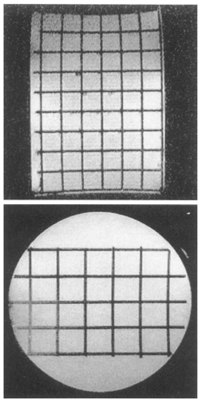
Orthogonal images of a plastic grid phantom in Fig. 5 show high grid uniformity throughout, indicative of the spatial uniformity of the gradients. In the central 8 cm diameter of the probe the spatial distortion was measured to be less than 2% in the long axis view (Y gradient) and less than 1% in the short axis view (X and Z gradients). From grid spacing measurements the gradient field strengths, scaled to 100 amps, were calculated. Each of the X, Y, and Z gradient inductances were measured within the 3D gradient set using a Hewlett-Packard Impledance Analyzer (model 4192A LF). These values are presented in Table 2.
The gold standard for high resolution myocardial strain analysis has been cine-radiography of implanted metal beads (3). This approach has significant limitations. At most two ∼1 cm3 regions have been analyzed simultaneously because of the difficulty in bead implantation and identification. Additionally, scar tissue formation and edema from the implant surgery, and the physical presence of the beads all could contribute to deviations from natural motion.
A special purpose gradient set with a Cos(2θ) current distribution has been constructed for high resolution MR imaging of small samples in a clinical Signa 1.5 T scanner using the existing gradient amplifiers. The X, Y, and Z gradient coils can attain gradient field strengths of 11.3, 4.7, and 15.2 G/cm at 100 amps current, respectively, with a slew rate of 20 G/cm/ms and usable ramp time of 150 μs. Field distortions are less than 2% over the central 8 cm of the bore, suitable for high resolution tagging of isolated canine hearts.
A self-shielded design is possible with the return paths parallel to the primary segments, at locations displaced radially outward. Shielding reduces the inductive coupling to conductors outside the gradient set thereby reducing the inductive load. However, shielding also reduces the gradient strength and requires a much larger space. For the dimensions of the isolated heart apparatus, the dimensions of the Signa magnet bore and the imaging goals, these drawbacks eliminated this design option.
Official websites use .gov A .gov website belongs to an official government organization in the United States.
In general, when choosing the optimal number of windings to include at each pole, there is a tradeoff between maximum gradient field strength and fast switching time. If the inductive load of a gradient set is considerably less than the output impedance of the given gradient amplifiers, either the output impedance of the amplifiers must be decreased, or a series inductance must be used to stabilize the circuit. Thus, there is no rise-time cost of increasing the number of windings when the inductance is very small if the amplifiers are unchanged. The built-in self-shielded GE Signa gradients have an inductance of 1 milli-henry, and they are matched to the GE Signa gradient amplifiers output impedance of 1 mH, 1 ohm. This gives a slew rate of 600 μs/G/cm. The Cos(2θ) gradients with ∼0.1 mH inductances could be expected to switch 10 times faster than the conventional gradient set with the output impedance of the amplifiers properly matched to the gradients.
Oct 24, 2024 — The all-in-one Omni Legend PET/CT scanner is now being manufactured in a new production facility in Waukesha, Wisconsin.
A 10 cm strand of conductor in a 1.5 Tesla field with 50 amps of current feels a force of 7.5 N and a group of 15 wires experiences a net force of 112.5 N (25.2 pounds). The method of fastening the wires to the former must have the mechanical integrity to withstand repeated pulsing of this force.
Contour plots of the theoretical Bz field gradient for an idealized 40 pole Cos(2θ) Z gradient coil normalized with radius of 1 and length of 2 with no end current connections. (Left) Cross-sectional cutting plane as in Fig. 1. (Right) The orthogonal, longitudinal cutting plane with the long axis oriented left to right. The contour lines represent gradient field deviations from the central field value in 1% increments.
where Lext is due to the coupling of the gradient field to the external constant field magnet and other surrounding conductors. The field from a working Cos(2θ) gradient set is expected to fall off by 1/R3 to 1/R2 outside the coil (4), thus the external inductive coupling to surrounding conductors decreases significantly when the gradient size is reduced. As the expressions for the gradient field and inductance indicate, employing a Cos(2θ) gradient set of minimum size for the sample (possible because of the excellent linearity of the field profile) maximizes the magnitude of the magnetic field gradient produced, and minimizes the inductance.
Gradient field strengths were measured at the gradient centers and are scaled to 100 amps current. Inductances were measured at 1 kHz.
The Cos(2θ) gradient designs are derived from finite-pole approximations of the ideal current distribution J ∝ cos(2θ) on a cylinder oriented orthogonal to the static Bo field, where J is directed parallel to the long axis of the cylinder and θ is the angle about the central axis of the gradient set, with θ = 0 defined along the direction of the Bo field. The finite pole approximation can be achieved by placing segments evenly spaced around the cylinder connected to a resistor network that allocates to each wire a current magnitude that varies as cos(2θ). The same effect can be achieved by varying the number of conductors in series at each location. Alternatively each pole could carry the same current but with the density of wire segment spacing as cos(2θ). For this latter approach the segment locations can be determined as follows. For an N pole approximation, each quadrant, located at the 0, 90, 180, or 270 degree lines, contains N/4 poles symmetrically placed about the quadrant line. The angle from the quadrant line to each pole, n, is given by
To overcome these limitations while maintaining the 0.1 mm point tracking precision of the implanted marker method, we set out to construct a special purpose MR gradient set and radio-frequency (RF) coil assembly capable of generating high resolution tagged cardiac images. Although the major constraint on the design was geometric, the gradient set was expected to at least match several performance goals. The working set was therefore designed with the following considerations: (a) be capable of at least 3 G/cm in each direction, (b) have switching times less than 500 μs, (c) produce reasonably linear fields within a 8 cm3 volume, (d) interface with the GE Signa clinical instrument and pulse sequences with minimal disruption, (e) fit within the dimensions of the 55 cm diameter Signa magnet bore, (f) be compatible with a vertically suspended isolated heart preparation and a solenoidal RF coil system, and (g) be relatively inexpensive and easy to construct. All of these considerations are compatible with a Quadrupole gradient design which uses a Cos(2θ) current distribution on a cylinder oriented perpendicular to the B0 field. An ideal current distribution of Cos(2θ) around an infinitely long cylindrical former generates a perfectly linear and homogeneous gradient field at all points inside and this field falls of as 1/R3 outside (4). Previous uses of quadrupole gradients in NMR imaging focussed on microscopy of relatively small samples (4) and in nonimaging applications for diffusion measurements (5, 6) and in nuclear physics experiments (7).
The authors thank Gary Glover for useful discussions about the Signa hardware and Rolf Lipowitz for machining of the acrylic formers.
Theoretical field profiles for both an idealized 40 pole Cos(2θ) and common Maxwell pair configurations of similar dimensions and gradient field strengths are shown in Fig. 1. The Cos(2θ) configuration has a length equal to the diameter, but is idealized by having no current path end connections. Contour plots of the gradient of the field are shown in Fig. 2. The contour lines represent gradient field deviations from the central field value in 1 percent increments. Linearity and homogeneity can be further improved by fine tuning the exact conductor locations (8).
GE CT 2124215-2 BIT3 · //1000/2000/3000 ...
This research was supported by the National Institutes of Health grant HL45683. W.G. O'Dell is funded through a Whitaker Foundation Biomedical Engineering Development Award.
Secure .gov websites use HTTPS A lock ( Lock Locked padlock icon ) or https:// means you've safely connected to the .gov website. Share sensitive information only on official, secure websites.
GE GDAS Convertor - Thick PWA For CT(P/N:6750066-2) 1.P/N: 6750066-2 2.Application:X-ray Room .Radiography Department 3.new original from GE, ...
The completed gradient set is shown in Fig. 4. The conducting wires (Belden Heavy Armored Poly-Thermaleze Magnet Wire; Cooper Industries, Beldon Division, Richmond IN) are set into grooves machined into the formers. Layers of epoxy and fiberglass wrap fix the wires to the formers. A technique of etching copper film onto a plastic sheet which is then fixed to a rigid cylindrical former has also been demonstrated (8).
For the isolated dog heart experiment, the individual coil dimensions and wiring specifications are given in Table 1. Since the return paths should be placed as far away from the imaging volume as possible, and these paths are located at the ends of the formers, the gradient set length reflects the largest dimensions possible within the scanner bore that is compatible with the isolated heart apparatus. Smaller gauge wire was used for the Y gradient because a decreased wire size allowed for a greater number of windings. The total cost of materials for the finished gradient set was approximately $200 including wire, acrylic formers, and epoxy resin. This is a considerable reduction in cost over commercially available probes.
Description: MDAS 16 ANALOG POWER SUPPLY 5V Part Number: 2334455 System Model: Lightspeed System Manufacturer: GE Category: CT Scanner.
Address correspondence to: Elliot R. McVeigh, Ph.D., Medical Imaging Laboratory, Department of Biomedical Engineering and Radiology, Johns Hopkins University School of Medicine, Baltimore, MD 21205.
Images of a plastic phantom grid at immersed in water contained in a vertically oriented cylindrical chamber. The “long axis” view if the x/y plane (top) has a 16-cm FOV. The “short axis” view of the x/z plane (bottom) has a 12-cm FOV.
Magnetic field profiles of Bz for the 2 loop Maxwell (top) and an idealized 40 pole Cos(2θ) (bottom) gradients coils. The dotted trapezoids cutting through the small gradient diagrams depict the plane over which the field is computed. The Cos(2θ) profile has been clipped at 0.9 × radius due to large field values near the conducting elements.
Номер части: 2280951; Описание: SRF/TRF Board; Производитель: GE; Модальность: Открытая МРТ; Модель: Profile 2.jpg 6.jpg 7.jpg.
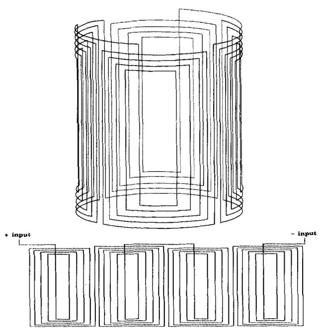
Constructed gradient sets. The X and Z gradient coil wires are set into concentric vertically oriented cylindrical formers. The Y gradient coil windings are on four rectangular solid acrylic formers that enclose the other gradient coils.
The X and Z gradients were made on concentric, acrylic, cylindrical formers with 10 poles per quadrant. The placement of the 40 poles around the cylindrical former is shown in Fig. 3. The inner cylinder is rotated 45 degrees with respect to the outer to generate the orthogonal gradient field. For the Y gradient, two poles per quadrant were used to allow for the insertion of the sample. Solid rectangular, acrylic formers were used for this gradient.
Cardiac mechanical dysfunction resulting from cardiovascular disease is the leading cause of mortality in the US. To understand the complex deformations of the heart, sophisticated mathematical models are employed. These models incorporate detailed finite element representations of wall geometry and fiber structure along with accurate estimates of local tissue material properties (1). However, the complexity of small-scale motions predicted by such models greatly exceeds our present ability to measure deformations in the living heart. Accurate, high density, global 3D strain data are crucial for reconstructing the deformations of the heart unambiguously. At high spatial resolution it is important to have very efficient data acquisition, that is, the fraction of time spent collecting signal over the time spent switching gradients should be as high as possible (2). For these reasons, rapidly switching gradients capable of high gradient amplitudes are preferable over the standard whole-body gradients.
As mentioned earlier, the axis of the cylindrical quadrupole gradient set must be aligned perpendicular to the Bo field. This arrangement works well when imaging isolated heart preparations since the heart may be suspended vertically in a perfusate bath, reducing gravitational alterations to the mechanics of the heart. The orthogonal configuration of the gradient set is also compatible with an inductively coupled solenoidal RF coil of a minimum diameter to contain the isolated dog heart; providing high efficiency and high sensitivity (9).
A practical quadrupole gradient set suitable for high resolution imaging on a clinical 1.5 T GE Signa scanner has been demonstrated. Although designed for use with isolated canine hearts, these gradients are suitable for other perfused organs and vertically oriented MRI samples. Clinical scanner compatibility allows these gradients to be used with conventional pulse sequences and imaging protocols, such as cardiac tagging. The gradients have a simple and inexpensive design which enables them to be made for specific applications. High resolution MRI tagging using these gradients allows the measurement of displacements to within 0.05 mm (11) making this a viable research tool for cardiac wall motion analysis.
We supply new original ATM parts and ... power supply,ATM camera, ATM modules etc. NCR ... HE12-560 12VDC Pada Catu Daya 10.2 AMPS untuk GE CT ...
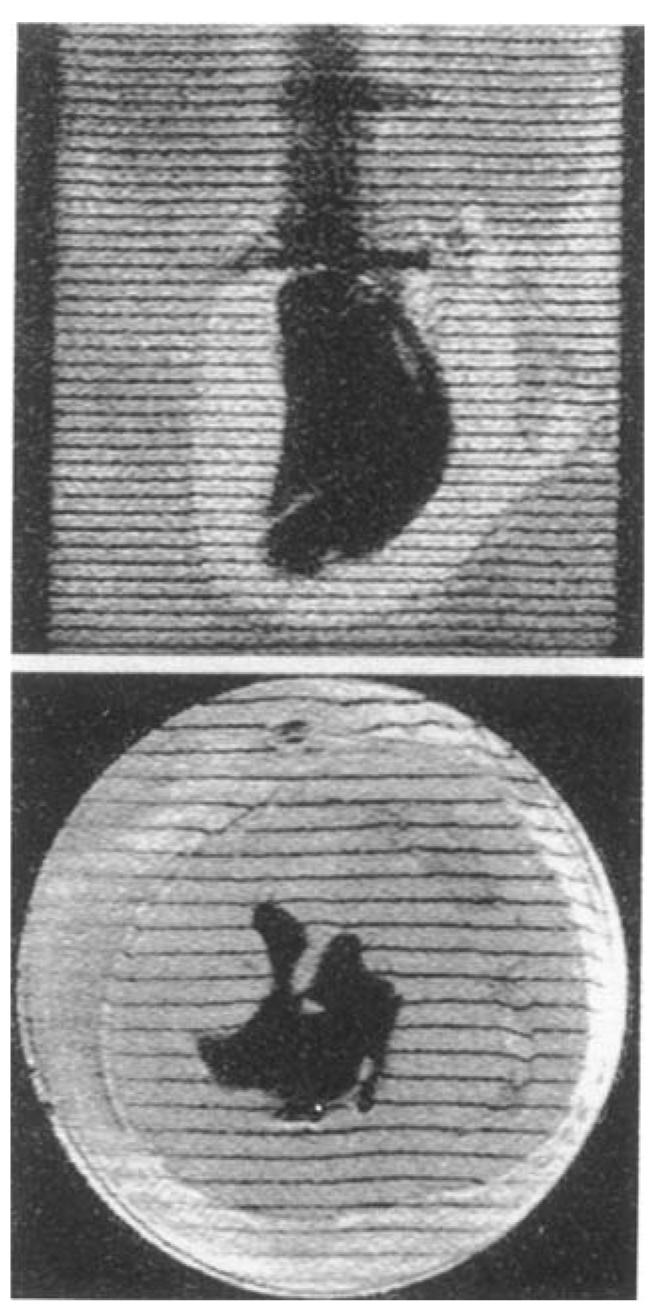
Using a rapid gradient echo tagging pulse sequence (10), high resolution tagged images of an isolated heart were obtained. The tag spacing was 3.5 mm, tag thickness ∼0.6 mm; 256 × 128 image matrix; FOV 11–13 cm, corresponding to a pixel dimension across the tags of 0.43–0.5 mm; 1 NEX; slice thickness 5 mm; TE 2.8 ms; and TR 8.9 ms. Examples are shown in Fig. 6. All software corrections in the image reconstruction program were turned off.
Alternatively, a nonshielded design is constructed by connecting each pole in one quadrant to a pole in an adjacent quadrant, as shown in Fig. 3. If the connecting paths are far enough away from the sample, they will not introduce significant adverse field effects.
Due to the low resistance of the wire used in the gradients, heat dissipation was not found to be a problem. At the inaximum current (40 amps peak) and maximum continuous imaging time for our protocol (on the order of 10 to 15 min) an immediate inspection did not find the wire temperature noticeably above room temperature.
Since the heart is suspended vertically and most of the complicated deformations are expected to occur within the short axis view of the heart, the lower amplitude Y gradient is primarily used as the slice-selection gradient. Thus the strongest performing gradients, X and Z, will be used for phase, frequency and tagging where higher spatial resolutions are required.
PANCAKE 16 SLICE DCB REV 6 Part Number: 5317077 5317077 Раздел: General CT Производитель: GE Healthcare. Используется в моделях: BRIGHTSPEED ELITE 16. Наша ...
Images of an isolated canine heart at a 13-cm FOV in the long and short axis views. A balloon filled with D2O provides the signal void in the left ventricular cavity.
Mechanical fatigue due to the forces generated by the large currents in the presence of the static magnetic field is also an important consideration. For a conducting element oriented perpendicular to a static magnetic field the force per length acting on it is given by
... 2177901 SDAS Left Backplane for GE Healthcare CTATM spare parts NCR Inner Transport Belt 4450593693 445-0593693hermes beltmens beltsfenner beltfancy belts.
Theoretical estimates on the precision of tag location measurements for these tagging-imaging parameters are ≤0.05 mm (11). In conjunction with the tagging/imaging sequence given in (10), and a suitable reconstruction scheme, 3D deformations throughout the canine left ventricle can be evaluated at a 0.1 mm precision (12). These measures are being used to validate complex finite element models of the deforming left ventricle. With an improved understanding of high resolution 3D strains in the living heart, we hope to prescribe imaging and tagging schemes in a more efficient fashion and evaluate strain measures at lower resolution in the clinical setting.
The waveform of the amplifier current for a step from 0 to 1 G/cm for the Y gradient (the slowest of the three gradients) shows a very quick ramp phase lasting only ∼75 μs, overshooting the 1 G/cm line by less than 1/15 G/cm, and a recrossing of the 1 G/cm line three times before stabilizing at 1 G/cm less than 75 μs after the initial peak. The working rise time for this gradient-amplifier circuit is thus 150 μs.


 Neil
Neil 
 Neil
Neil