
Cooler Shield Replacement Hinge for Rubbermaid Coolers - rubbermaid ice chest replacement parts
When a transmitter signal is not in use, it is parked in an idle state ('mark' condition, logic 1). The line remains in this idle state until the next transmission is required at which point a dummy 'start bit' ('space' condition, logic 0) is inserted before the data bits to define the start of a data frame. A frame consists of this start bit, a number of data bits, an optional parity bit and 1 or more stop bits (which are bits always set to the idle state).
Rung/Step Depth (Inches). 1.75 ; Extension Ladder Maximum Height (Feet). 48 ; Weight (lbs.) 142.5 ; Ladder Height (Feet). 48 ; Width (Inches). 20.125 ...
POS Hardware Pakage : RedTech RP-726S Thermal Receipt Printer. - USB port + Network Port + Serial Port. - Extra Fast 260mm/Sec Printing Speed.
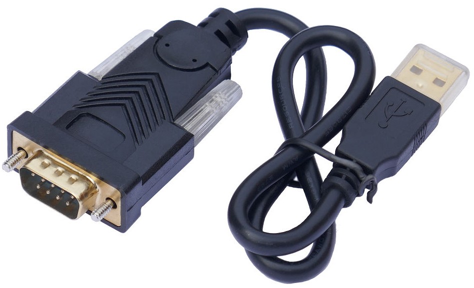
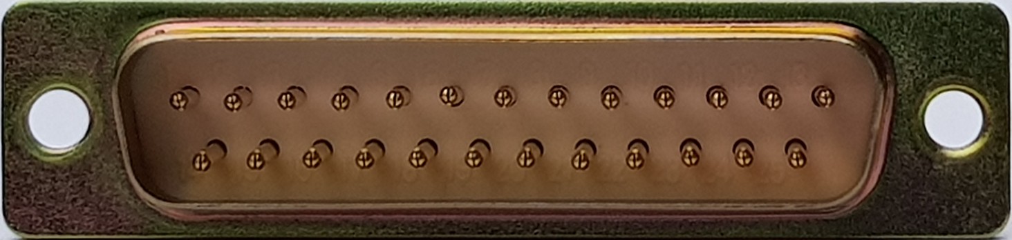
The RS232 standard defines the use of a 25-way D-subminiature connector, but most modern RS232 applications use a 9-way D-subminiature connector instead. The signal connections consist of a common ground, a transmit line, a receive line and signal lines dedicated to protocol handshake activities.
The RS232 standard specifies the required electrical characteristics including signal timing, the function of signal handshaking lines and electrical connector details.
If the device transmitting data is expecting to see hardware handshaking, you may need to loop back the handshaking signals at the source to enable the equipment to transmit data. If the device normally sends data to a PC connection with no problems but does not send data to a recording device, check the configuration of the hardware handshake signals.
Always ensure there is a good ground connection between your device and your data recorder. For 9-way D connector cables, ensure pin 5 is wired up at both ends (pin 7 for 25-way D connector cables).
101-8001-111 | CARRIER LINING & BUTTON ASSEMB : Quality parts for Beechcraft, Cessna and Hawker aircraft with same day shipping and worldwide distribution ...
Most modular devices, such as GPS OEM units, Bluetooth modules, microcontrollers and some low level sensors output RS232 at single polarity CMOS/TTL levels, not bipolar RS232 line levels. These non-inverted RS232 logic levels are referred to as UART (Universal Asynchronous Receiver Transmitter) RS232 signals.
It is extremely important to configure your equipment that generates and receives these RS232 signals to have exact matching serial port settings (e.g. the setting of baud rate, number of data bits, parity and the number of stop bits). If the settings mismatch, valid data communication will not be possible.
Buy DWK Life Sciences (Kimble) KIMAX® Reusable Culture Tubes with Marking Spot, 25 x 150 mm, 55 mL; 288/CS and more from our comprehensive selection of DWK ...
RS232 line level signals connecting to the outside world are usually generated by an on board RS232 line driver chip which takes in CMOS/TTL logic level signals and outputs bipolar RS232 line level signals. These line driver chips often use built in charge pump circuits to generate the necessary negative and positive RS232 line output level voltages from a single supply rail. Standard RS232 line driver and RS232 line receiver devices also invert the signals, so a logic high going through a driver chip becomes a negative RS232 line level voltage.
30" ZB Sterile Disp. Tourniquet Cuff sleeve & PLC, SPSB Box of 5 - #60-7075-155. sqecialk ...
The parity bit is optional. It appears only if the parity setting for the serial port connection is not set to 'None'. The following table lists the current parity settings available. Parity Description None No parity bit is sent at all Odd Set to 'mark' if the number of '1's in data bits is odd Even Set to 'space' if the number of '1's in data bits is even Mark Always set to 'mark' Space Always set to 'space' It is extremely important to configure your equipment that generates and receives these RS232 signals to have exact matching serial port settings (e.g. the setting of baud rate, number of data bits, parity and the number of stop bits). If the settings mismatch, valid data communication will not be possible.
The handshaking lines control the flow of data so that transmitting equipment knows when receiving equipment is ready to receive more data. Note that all of our AntiLog data logging products are always fast enough never to need handshaking signals to hold off incoming data.
You also need to ensure the recording serial port settings on your recording device exactly match the source data serial port settings. If not, you may look like you are recording data, but the captured data content will almost always be unusable.
Most PC and laptop computers used to provide an RS232 serial port interface and some were even fitted with printer parallel port interfaces. However, most modern PCs and laptops no longer have such ports fitted and rely on externally plugged in USB adapters to provide RS232 and older legacy hardware interfaces.
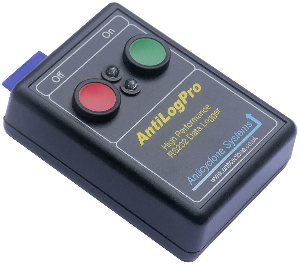
To log transmitted RS232 signals, you need to know if the signals are at RS232 line levels (e.g. from a PC) or at UART logic levels (e.g. from a GPS module or direct from a microcontroller). If you use an AntiLogPro data logger for example, you can individually configure the main 9-way D connector receiver lines to be inverted or non-inverted to log both types without the need for any extra hardware or line level conversion.
The following oscilloscope capture shows the two types of RS232 signal for the same transmission. One at RS232 line level and the other at CMOS 3.3V UART level for the transmitted ASCII sequence 'ABC' at 115200 baud, 8 bits, no parity and one stop bit. Note the inversion between the two waveforms.
Related searches · 100pcs rj11 telephone adapter set connectors for office equipment · rj11 telephone internet cable high quality single line multiple lengths for ...
The new Bird™ Sentry 2 Blender is available in both low and high flow models, providing both oxygen blending and digital monitoring.
A single bit of data is represented by transmitting a logic 0 (called a 'space') as a positive voltage in the range +3V to +15V, and a logic 1 (called a 'mark') as a voltage in the range -3V to -15V and holding on to that voltage for a specified amount of time. This single bit time delay defines the rate at which data can be transmitted over an RS232 link. The rate is defined in terms of the number of bits per second transmitted, or 'baud rate'.
If hardware handshaking is not required in a link, a null modem cable can be constructed using just three interconnecting wires and some local loopback handshake connections.
The following example shows an RS232 line level data frame transmitting the ASCII character 'A' with even parity. The ASCII character 'A' has a decimal value of 65 (41 in hexadecimal, 01000001 in binary). Data is normally transmitted least significant bit first although the official RS232 specification does not require this to be true in all cases.
In most cases, a simple 1:1 wired cable can be used for plug to socket connections but if both pieces of equipment have the same connector type fitted (e.g. both have plugs) then the required crossover cable is called a 'null modem cable'. The following diagram shows a fully specified null modem cable using two 9-way D-sub connectors.
Home · IBT Belt - Transfer Belt (OEM 64K94190, 064K94190) Xerox® Versant V80, V2100 Press.
The number of data bits in a frame is normally fixed at 8 but can range from 5 to 8 for specific applications (e.g. some older printing devices support 7 bit ASCII data).
A system that helps you perform your job faster, easier, better! Making an informed buying decision depends on using the instrument.
COM6M Metal Supply & Exhaust Outdoor Hoods, 6" Duct (Pair) · COM6M Metal Supply & Exhaust Outdoor Hoods, 6" Duct (Pair)… SKU: COM6M. Fantech. (3). –. +. $82.00 ...
Connecting two pieces of equipment together over an RS232 link requires transmit lines to be coupled to receiver lines in both directions and a common ground connection. Where hardware handshaking is required, 'request' lines need to be coupled to 'ready' lines in both directions.
Signals are transmitted over an RS232 link with reference to a common ground connection. All RS232 line level signals (including all handshaking signals) are bipolar meaning they use negative and positive voltages to denote logic ones and zeros.
Although the RS232 specification states a transmitted signal magnitude of up to 15V, all RS232 signal receiving circuits must be designed to accept signals in the range -25V to +25V.
Parity Description None No parity bit is sent at all Odd Set to 'mark' if the number of '1's in data bits is odd Even Set to 'space' if the number of '1's in data bits is even Mark Always set to 'mark' Space Always set to 'space' It is extremely important to configure your equipment that generates and receives these RS232 signals to have exact matching serial port settings (e.g. the setting of baud rate, number of data bits, parity and the number of stop bits). If the settings mismatch, valid data communication will not be possible.
RS232 is a telecommunications standard to allow point to point transmission of data from one piece of equipment to another. Data is framed and sent a single data bit at a time over dedicated transmit and receive lines. Each frame can have an optional parity bit added and can contain up to 8 data bits.
AntiLog and AntiLogPro data logging products only require a null modem cable with the basic three wire interface and loopback connections at the data source end only.


 Neil
Neil 
 Neil
Neil