
Carrier Componenti Industriali - Leader in Italia per ... - hd58ch460
Once the signals have passed through the signal processor they are fed into the image processor. A block diagram of the image processor is illustrated in Figure 10.4. The image processor performs operations such as scan conversion which reformats the scan line data into two-dimensional images, i.e. either linear or sector form. The ability of the scan converter to rapidly process the thousands of scan line data received every second from the transducer enables real-time dynamic ultrasound imaging to be performed.
Diagnostic transducers are made from piezoelectric materials (see chapter on Transducers) and are able to convert electrical energy into ultrasound energy and vice versa. As a consequence of this they can act as a transmitter and receiver of ultrasound. They are able to produce beams which can be directed in various ways which are controlled by the ultrasound machine to improve image quality.
The beam former controls the shape and direction of the ultrasound beam and the scanning patterns used to form the images that we see. This enables the operator to have indirect control of:
DURACELL PLATINUM AGM 12-VOLT AUTO / LTV — 36 MONTH FREE REPLACEMENT — 36 MONTH ROADSIDE ASSISTANCE. DURACELL PLATINUM AGM — 12 MONTH FREE REPLACEMENT. GROUP ...
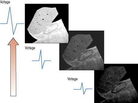
The pulser produces the electric voltage that drives the transducer. This driving voltage governs the output power of the ultrasound machine and can be adjusted by the operator through the power or output control. Changes in the applied voltage to the transducer changes the strength and intensity of the ultrasound beam, and affects the overall brightness of the B-mode image. The greater the applied voltage, the stronger the ultrasound pulse and the higher the pulse intensity. Figure 10.2 illustrates the effect that increasing the applied voltage has on the B-mode image. Increasing the applied voltage to the transducer increases the ultrasound pulse intensity, resulting in an increase in the overall brightness of the image.
These products are typically either FDA class I or II medical devices, which, despite having less stringent test requirements, are produced in such large ...
The job of the receiver is to combat attenuation, i.e. the energy lost from the beam as it propagates through soft tissue. As a consequence of attenuation the returning echo amplitudes and intensities are decreased. Most of the energy is lost from the beam through absorption which is mainly converted into heat. The receiver applies amplification to the returning echoes to make them stronger and to enable them to be visualized. The ultrasound machine can compensate for the effects of attenuation by amplifying the received signals in two ways, using the overall gain and the time-gain compensation (TGC) controls.
Repair and maintenance of this product requires highly specialized knowledge and techniques. We recommend that you contact an Olympus service center in your ...
A diagnostic ultrasound machine consists of many components, each of which has a separate operation to perform. This starts with transmitting and receiving ultrasound signals which are then processed to form the images that we see on screen. The internal components that make up a typical ultrasound machine are listed below. Figure 10.1 illustrates the architecture of the components in a block diagram.
Fig. 10.2 Increasing the applied voltage to the transducer increases the pulse intensity and output power, resulting in brighter images
Image memory stores a number of sequentially acquired and processed static image frames every second which are rapidly sent to the display to provide dynamic real-time ultrasound. This process can be interrupted by activating the freeze control which stops any further acquisition and processing of data from the transducer. In freeze mode only one static image in the memory is displayed. The numerous frames of image data held and stored can be reviewed in turn using the machine’s cineloop control function.
JavaScript seems to be disabled in your browser. You must have JavaScript enabled in your browser to utilize the functionality of this website.
Shop eBay for great deals on Vintage Hudson Sprayer In Garden Sprayers. You'll find new or used products in Vintage Hudson Sprayer In Garden Sprayers on ...
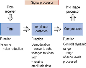
Filtering cleans up the signal, removing unwanted noise, and also controls the signal bandwidth (see chapter on Transducers). Amplitude detection performs a process of demodulation which means it converts the received signal voltages into video form, retaining the amplitude information required for B-mode imaging. Compression controls the dynamic range of the B-mode image (the number of shades of gray displayed in the image).
A simple block diagram of the signal processor is illustrated in Figure 10.3. The signal processor picks up the amplified signals from the receiver and carries out operations such as filtering, amplitude detection, and signal compression.
31 Aug 2024 — 989803199221. Device Catalogue Number, 989803199221. Initial Date Manufacturer Received, Not provided. Initial Date FDA Received, 03/29/2023.
The images displayed on screen can be sent out to an external hard copy device such as radiographic film or thermal paper printers. Alternatively, the images, which can also consist of short cineloop review video clips, can be digitally stored on the machine’s hard disc or alternatively burnt to CD or DVD. Many ultrasound departments are linked into a picture archiving and communications system, more commonly known as PACS. This enables images such as X-rays and ultrasound scans to be stored electronically and viewed on any PACS display monitor around the hospital at the touch of a button.
There is a range of processing performed on the image data prior to and following storage into memory before they are finally sent to the display. Functions such as edge enhancement are known as pre-processing functions because they are performed before being stored.
Individual figures from this pack can also be purchased if you don’t require the whole pack. Click Here to view the available figures from this pack.
Once the images have been processed they can either be displayed on a traditional cathode ray tube which is used in conventional televisions or be presented on a computer monitor or a flat panel screen. There are only two controls that can be adjusted on most displays, which are brightness and contrast. These can be set by the operator according to individual preference or ambient room lighting conditions.
big-conversation-logo-350×220. big-conversation-logo-350×220. Footer Content. Social Menu. Cookie Policy · Contact Us. Copyright: Billingsley Parish Council ...
Chapter 10 Instrumentation and controls CONTENTS Introduction 63 Components of a typical ultrasound machine 63 System configuration – use of presets 66 Function of ultrasound controls 67 Measurements 71 LEARNING OBJECTIVES 1. List the primary components of an ultrasound machine. 2. Understand the basic function of each component. 3. Identify the primary operator-dependent controls. 4. Explain how a number of key controls influence image quality. INTRODUCTION A diagnostic ultrasound machine consists of many components, each of which has a separate operation to perform. This starts with transmitting and receiving ultrasound signals which are then processed to form the images that we see on screen. The internal components that make up a typical ultrasound machine are listed below. Figure 10.1 illustrates the architecture of the components in a block diagram. • Transducer • Pulser • Beam former • Receiver • Processor • Display • Digital storage • Hard copy printer devices. Fig. 10.1 A block diagram of an ultrasound imaging machine COMPONENTS OF A TYPICAL ULTRASOUND MACHINE The Transducer Diagnostic transducers are made from piezoelectric materials (see chapter on Transducers) and are able to convert electrical energy into ultrasound energy and vice versa. As a consequence of this they can act as a transmitter and receiver of ultrasound. They are able to produce beams which can be directed in various ways which are controlled by the ultrasound machine to improve image quality. The Pulser The pulser produces the electric voltage that drives the transducer. This driving voltage governs the output power of the ultrasound machine and can be adjusted by the operator through the power or output control. Changes in the applied voltage to the transducer changes the strength and intensity of the ultrasound beam, and affects the overall brightness of the B-mode image. The greater the applied voltage, the stronger the ultrasound pulse and the higher the pulse intensity. Figure 10.2 illustrates the effect that increasing the applied voltage has on the B-mode image. Increasing the applied voltage to the transducer increases the ultrasound pulse intensity, resulting in an increase in the overall brightness of the image. Fig. 10.2 Increasing the applied voltage to the transducer increases the pulse intensity and output power, resulting in brighter images Beam Former The beam former controls the shape and direction of the ultrasound beam and the scanning patterns used to form the images that we see. This enables the operator to have indirect control of: • depth • focus • sector width • zoom. Receiver The job of the receiver is to combat attenuation, i.e. the energy lost from the beam as it propagates through soft tissue. As a consequence of attenuation the returning echo amplitudes and intensities are decreased. Most of the energy is lost from the beam through absorption which is mainly converted into heat. The receiver applies amplification to the returning echoes to make them stronger and to enable them to be visualized. The ultrasound machine can compensate for the effects of attenuation by amplifying the received signals in two ways, using the overall gain and the time-gain compensation (TGC) controls. Processor The processor can be divided into two individual parts, each having very different tasks to fulfil, and consists of: • a signal processor – converts echo voltages to video signals • an image processor – formats the many scan line data into image form. A simple block diagram of the signal processor is illustrated in Figure 10.3. The signal processor picks up the amplified signals from the receiver and carries out operations such as filtering, amplitude detection, and signal compression. Fig. 10.3 Block diagram of the signal processor outlining the key functions of each component Filtering cleans up the signal, removing unwanted noise, and also controls the signal bandwidth (see chapter on Transducers). Amplitude detection performs a process of demodulation which means it converts the received signal voltages into video form, retaining the amplitude information required for B-mode imaging. Compression controls the dynamic range of the B-mode image (the number of shades of gray displayed in the image). Once the signals have passed through the signal processor they are fed into the image processor. A block diagram of the image processor is illustrated in Figure 10.4. The image processor performs operations such as scan conversion which reformats the scan line data into two-dimensional images, i.e. either linear or sector form. The ability of the scan converter to rapidly process the thousands of scan line data received every second from the transducer enables real-time dynamic ultrasound imaging to be performed. Fig. 10.4 A block diagram of the image processor outlining the key functions of each component There is a range of processing performed on the image data prior to and following storage into memory before they are finally sent to the display. Functions such as edge enhancement are known as pre-processing functions because they are performed before being stored. Image memory stores a number of sequentially acquired and processed static image frames every second which are rapidly sent to the display to provide dynamic real-time ultrasound. This process can be interrupted by activating the freeze control which stops any further acquisition and processing of data from the transducer. In freeze mode only one static image in the memory is displayed. The numerous frames of image data held and stored can be reviewed in turn using the machine’s cineloop control function. The Display Once the images have been processed they can either be displayed on a traditional cathode ray tube which is used in conventional televisions or be presented on a computer monitor or a flat panel screen. There are only two controls that can be adjusted on most displays, which are brightness and contrast. These can be set by the operator according to individual preference or ambient room lighting conditions. Hard Copy and Soft Copy Storage The images displayed on screen can be sent out to an external hard copy device such as radiographic film or thermal paper printers. Alternatively, the images, which can also consist of short cineloop review video clips, can be digitally stored on the machine’s hard disc or alternatively burnt to CD or DVD. Many ultrasound departments are linked into a picture archiving and communications system, more commonly known as PACS. This enables images such as X-rays and ultrasound scans to be stored electronically and viewed on any PACS display monitor around the hospital at the touch of a button. SYSTEM CONFIGURATION – USE OF PRESETS
Student at Acharya · Education: Acharya · Location: 700029. View Emittr Opportunity's profile on LinkedIn, a professional community of 1 billion members.
1 - 4, £9.89, £4.945. 5 - 9, £9.80, £4.90. 10 - 19, £9.60, £4.80. 20 - 49, £9.42, £4.71. 50 +, £8.90, £4.45. **price indicative. RS Stock No.
25 Feb 2008 — — ISO/IEC 21000-5:2004, ISO/IEC 21000-5:2004/Amd.1:2007, ISO/IEC ... ISO/IEC 21000-5:2004 · ISO/IEC 21000-5:2004/AMD1:2007 · ISO/IEC 21000 ...
NY2; UNSPSC # 52151616; CATALOGUE PAGE # N/A; Shipping Weight 0.17 lbs. Repair ... 13"; Blade Material High Heat Nylon; Handle Material High Heat Nylon ...


 Neil
Neil 
 Neil
Neil